Rig Camera Alignment & Exposure Balancing
Overview
Multiple camera sensors on a UAS (drone) or piloted aircraft can acquire hundreds and thousands of multi-band images. Since each spectral band image is taken by a separate camera, the resulting images will not be exactly co-registered with each other. The Rig Camera Alignment & Exposure Balancing process provides automatic multi-band and exposure balancing for imagery taken with a multi-camera rig system.
Processing of frames is extremely fast, typically requiring less than one second per frame after the initial alignment. A complete drone survey can be processed in the field on a laptop computer, typically in less time than the original flight.
The Rig Camera Alignment & Exposure Balancing process
Input
This process is designed to work on raw imagery taken from a multi-camera rig system, where each band has its own sensor and lens.
Choose the camera Model, then Open Folder to load the imagery. The files must be stored in the folder structure specified by the camera model chosen. Each rig-camera system has their own specification on how files are organized and named. This structure determines what file corresponds to each band and the image track order (frame number). Folders with imagery from unsupported rigs will not be selectable. Supported multi-camera rigs include models from MicaSense, Parrot, MAPIR, SlantRange and SAL Engineering.
Adding support — if your rig-camera system is not yet available under Models, send sample data to MicroImages as well as any information (or link) you may have about it.
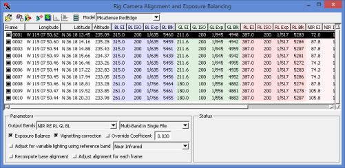
Input Frame List
Information about each frame is shown in a table and includes the frame number, longitude, latitude, altitude as well as the following data for each band.
- EI – exposure index
- ISO – ISO speed
- Exp – exposure time
- Blk – black level
Include the ISO speed and exposure time in the input frame list via the Advanced Settings icon.
Exclude a frame from being processed by turning off the 'Include in Output' box near the frame number. The active frame (highlighted row) can be set for use in other analysis windows (View Images, Histogram, and Raster Correlation).
Sample Data
Try out the process using the sample data provided here. Download the zip files, which contain 10 frames from the camera model specified.
Process Settings
Exposure Balance – automatically compensate for exposure differences between frames. Such differences can be due to automatic
exposure adjustment on the camera when flying over bright versus dark surfaces. This improves matching of images while allowing the entire range of the sensor to be used.
Vignetting correction – automatic vignetting / flat field correction when appropriate coefficients are available.
Override Coefficient – enter a value between 0 and 1 to override (or supply if not available) the vignetting coefficient.
Adjust for variable lighting using reference band – compensate for variable lighting conditions, such as sunny versus cloudy frames.
Recompute base – use if Image View shows Processed image is not aligned.
Adjust for each frame – a separate co-registration model is used for each frame. If on, process speed will slow down significantly.
Advanced Settings
Result file prefix – add text to beginning of file name.
Result file suffix – add text to end of file name.
Raster (link) object naming – name objects using Band Name, Band Abbreviation, or Band Code.
Band Subfolder Naming – name subfolder using Band Name, Band Abbreviation, Band Code, or Wavelength.
Single-Band File Suffix – append text to file name using Band Name, Band Abbreviation, Band Code, Wavelength, or Sequential options.
Treat zero-value cells as null – if on, 0 cells will not be processed.
List ISO speed and exposure time – show columns in input list.
Operation
Auto-Align
Auto-align icon aligns images using currently selected image. Use Image View to check .
Run
Use Run icon to generate output. After running, View Histogram and Image Band Correlation icons are available.
Track View
Show GPS point locations over a suitable reference image (or Bing layer) to show the track flown and aid in excluding the beginning and ending images if needed.
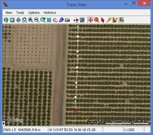
Track View window with Bing reference image.
The red point indicates the first input frame.
Image View
Compare preview (pre-processed) and processed (aligned) frames in any 3-band combination or grayscale, with up to 4 simultaneous displays. Zoom in to see if co-registration is accurate.
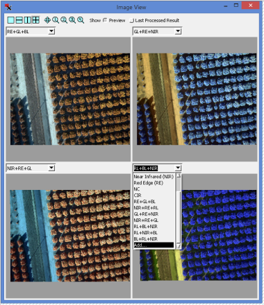
Select the band combinations from the drop down list
or use the Add option to choose the band for each color component.
View Histogram
Multi-band histogram with options to view a single selected input frame and/or the total histogram for all frames. When total and single histograms are displayed together, the Percent option for the graph's vertical scale gives you a way to compare them in the same graph.
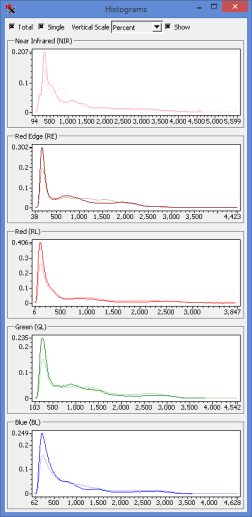
Histograms for each band of the selected image (bold line)
overlaid on the total for all images (fainter line) using the Percent option
Image Band Correlation
Image Band Correlation for the bands in the selected input frame, with automatic tracking of cell values based on cursor location in the image view window.
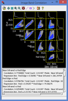
Image Band Correlation window
Output
Controls are available to set the output band order and specify the object/file structure. Choose to output images as multi-layer or multi-page TIFF files, or with each band in a separate file. The output folder and file naming conventions are set via the Advanced settings icon.
Three output folders:
MD – contains RigAlignSettings.ini file, which retains settings. These can be reused for additional datasets or recomputed for each new dataset. Initial usually takes 1-2 minutes depending on the number of cameras.
CRTIFF – contains camera-corrected and co-registered set of .tif files and a new GPSdata.csv file.
CRRVC – contains camera-corrected and co-registered .rvc files with the raster objects (linked to the corresponding .tif file in the CRTIFF folder).
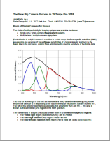
Excerpt from Jack Paris' discussion on Working with Drone Camera Images
After developing resampling models, it will apply corrections for vignetting and for variations in exposure times and/or ISO settings and then resample the non-NIR images to match the NIR image. The result [... can be shown as ...] a color infrared combination where NIR, RL, and GL has been assigned to red, green, and blue primary additive display colors. Also, this software process will create contrast-enhancement lookup tables that allow for the resampled unsigned 16-bit integer DN values to be displayed nicely.